Installing an extension loop in a single-valve system

Installing an extension loop in a single-valve system
Topic LCI-USG-0129, Last Updated 11/08/2024

In a single-valve system, the extension loop is installed between the pressure transducer and the sample needle.

  1. If system flow is running, stop the flow. On the touchscreen, tap COMMANDS, and then tap the pause button next to Flow is On.
  2. Open the sample manager fluidics door.
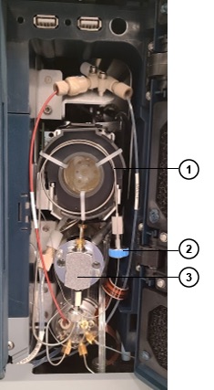
    Figure 1: Single-valve system
    Extension loop with holder
    Sample needle tool-free fitting
    Pressure transducer
    TFF adapter fitting
  3. Disconnect the tool-free fitting (TFF) that is attached to the extension loop and the sample needle. There is no need to remove the TFF adapter fitting from the pressure transducer.
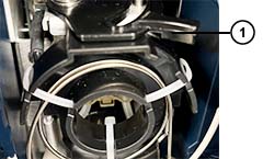
    Figure 2: Extension loop latch
    Extension loop latch
  4. Push the extension loop latch backward to release the extension loop holder and remove it from the sample manager.
  5. Install a different size extension loop between the TFF adapter fitting and the sample needle. There is no need to remove the TFF adapter fitting from the pressure transducer.
  6. Push the extension loop latch forward to secure the extension loop holder in the sample manager.
  7. On the touchscreen, tap System > Module configuration and follow the on-screen prompts to specify the extension loop volume configuration.
  8. On the touchscreen, tap Setup > Startup and follow the on-screen prompts to prime and prepare the system for use.

Need Help? Connect with a Waters expert. 


To avoid risk of personal injury and to prevent damage to laboratory equipment, always operate your Waters products in accordance with the applicable operational and safety information, your organization’s standard operating procedures, and local regulations.

Refer to the English version of this page for the latest information.

Back To Top Back To Top